Contents |
||
| Previous Tutorial | Back to Index | Next Tutorial |
|---|
|
|
|
|
|
|
|
|
The nightmare of graphic user interfaces (GUIs) is twofold: they require an enormous amount of intuition to operate them; and the results are
correspondingly sloppy. Recently, I wanted to design a few simple images to illustrate geometrical transformations for another tutorial
(Squaring the Circle with ImageMagick®) and although I had clear mathematical goals, accomplishing them
proved almost as difficult as inventing the wheel. What I needed was a way of communicating these precise mathematical concepts concisely
to a graphics generating program.
That is: I did not want to have to sit down with an editor and write script for Imagick, then switch to the browser and reload, and switch and edit
and reload page after page. Rather, I wanted to do the whole caboodle from the browser. If necessary, time after time. Nor did I want to have to
check the syntax and tweak parameters that were moot anyhow. But what I did want was a simplified version of the command line that would do what
I intended. And as some of those things would be a little more complicated in execution than others, I wanted to unify and simplify the commandos
to make the whole thing manageable.
So if you're wondering why the graphics experts in CSI are busy at the keyboard, rather than dragging the mouse around a lot, the solution
is: They're using InterDraw.
The topic of installing ImageMagick® and the Imagick DLL for PHP on your computer has been dealt with in the tutorial on ImageMagick® and Panorama Processing.
Picture this: A text box for typing in commandos, and a submit button that when pressed reloads the page with the executed graphic. Hey, that's all, folks! Except for implementing the interpreter and perhaps a couple of sanity checks.
The form used here has exactly just those two elements. Everything else will come from the user. Note that the wrap in the textarea named dcode is turned off, because InterDraw will interpret each line as a separate instruction and without wrapping overlength lines it is easier to see what belongs to each instruction.
<?php
extract ($_POST);
$b = "\r\n";
echo "<html>$b";
echo "<head>$b";
echo "<title>Lee Traynor's InterDraw</title>$b";
echo "</head>$b";
echo "<body>$b";
echo "<center><h2>Lee Traynor's InterDraw</h2>$b";
echo "<form method=\"post\" action=\"{$_SERVER["PHP_SELF"]}\">$b";
echo "<table>$b";
echo "<tr valign=\"top\"><th align=\"right\">Drawing Code:</th>$b";
echo "<td><textarea cols=\"60\" rows=\"12\" name=\"dcode\" scrollbars=\"auto\" wrap=\"off\">$b";
if (isset ($dcode)) echo $dcode;
echo "</textarea></td></tr>$b";
echo "<tr valign=\"top\"><td colspan=\"2\" align=\"center\"><input type=\"submit\" name=\"submit\" value=\"Draw!\"></td></tr>$b";
if (isset ($dcode))
{
#[This is where the fun will happen.]
}
echo "</table>$b";
echo "</form>$b";
?>
</center>
</body>
</html>
Our drawing code will be entered into the text box and handed over to PHP as $dcode. We will take every line of $dcode as an instruction to be interpreted into a drawing/graphic process.
The first step would then be to break up $dcode into an array, if it is set, and to break up each array further into components for the interpreter. The shell of our system will look like this:
if (isset ($dcode))
{
$dcode = explode ($b, strtolower ($dcode));
foreach ($dcode as $element)
{
$data = explode (" ", $element);
#[Here a switch element will follow to interpret every line]
}
}
After the loop we will want to do two things:
Before viewing the image these points will have to be taken into account:
echo "</table>$b<table>$b";
if (isset ($filename) and in_array ($format, array ("gif", "jpg", "png"))) echo "<tr valign=\"top\"><td align=\"center\" style=\"background-color:#CCCCCC\"><img src=\"$filename\"></td></tr>$b";
else
{
$im->writeImage ("temp.png");
echo "<tr valign=\"top\"><td align=\"center\" style=\"background-color:#CCCCCC\"><img src=\"temp.png\"></td></tr>$b";
}
$im->destroy ();
The data for each successful instance of our drawing should be saved to a text file for later perusal.
if (!isset ($filename)) $filename = ""; else $filename .= $b;
file_put_contents ("ID_Log.txt", date ("Y.m.d, H:i:s") . "$b" . trim (implode ($b, $dcode)) . "$b$filename--$b", FILE_APPEND);
Some hints have already become apparent in designing the shell that some basic tasks need to be addressed before starting to draw:
switch ($data[0])
{
case "new":
$im = new Imagick();
checkdata (array (640, 480, "transparent"));
$width = $data[1];
$height = $data[2];
$im->newImage ($width, $height, $data[3]);
break;
case "image":
if (isset ($im)) $im->destroy ();
array_shift ($data);
$file_im = implode (" ", $data);
$format = array_pop (explode (".", $file_im));
$im = New Imagick ($file_im);
list ($width, $height) = array_values ($im->getImageGeometry ());
break;
case "addimage":
array_shift ($data);
$x = array_shift ($data);
$y = array_shift ($data);
$file_im = implode (" ", $data);
$im_temp = New Imagick ($file_im);
$im->compositeImage ($im_temp, imagick::COMPOSITE_DSTOVER, $x, $y);
$im_temp->destroy ();
break;
case "save":
$im->writeImage ($data[1]);
$filename = $data[1];
$parts = explode (".", $filename);
$format = array_pop ($parts);
break;
}
The function checkdata () ensures that optional parameters are set to individually determinable default values if they are not explicitly specified:
function checkdata ($defaults)
{
global $data;
if (!is_array ($defaults)) $defaults = array ($defaults);
foreach ($defaults as $i=>$default) if (!isset ($data[$i + 1])) $data[$i + 1] = $default;
}
The first line of the drawing code could start with the word "new" in which case a new Imagick object would be created that would then also require two further parameters to be defined: $height and $width. A third parameter to define the background colour is optional. If it is not set, then the default is "transparent", which is preferable in any case (as will become clear in the course of the tutorial). The background colour can be dealt with with its own commando:
case "background":
$imtemp = new Imagick ();
$imtemp->newImage ($width, $height, $data[1]);
$im->compositeImage ($imtemp, imagick::COMPOSITE_DSTOVER, 0, 0);
$imtemp->destroy ();
break;
The other way of creating a new image would be to load an existing one with the word "image" which would carry with it its own height and width; but we would first need to see whether an image was already present, and, if so, destroy it. Alternatively, we could add an image onto an existing canvas.
Finally, Imagick allows a large number of graphics formats to be saved, simply by appending the appropriate ending to the file name. This graphic format can be retrieved for later use by extracting the file suffix, i.e the character string after the last ".".
Even with these three commandos we can already do useful work, e.g.:
Examples of InterDraw code
1. To transform one graphic format to another:
image file.jpg
save file.png
2. To paste an image onto an existing canvas:
new 640 480 none
addimage file.jpg 10 75 (adds image with topleft corner at 10, 75)
save paste.jpg
Warning! InterDraw has no mechanism to prevent files from being overwritten and it will overwrite files without asking.
Now before we get down to some actual drawing, let's consider a short-cut which will save us some work on the way:
As we will be setting the parameters of drawing objects (stroke colour, width, fill colour, and transparency) time and again, the question arises of writing a function that can be used for this, rather than having to write separate lines of code each time the task arises. In Object-Oriented Programming, this is achieved by extending the object by a new function; and in contrast to non-OOP where a value (e.g. array) is returned, the object itself is operated on and doesn't require returning. Our new object LTImagickDraw will thus be able to use this function:
class LTImagickDraw extends ImagickDraw
{
function ColorWidthFill ($color = "black", $width = 1, $fill = "none", $trans = 1.0)
{
$this->setStrokeAntialias (true);
$this->setStrokeColor ($color);
$this->setStrokeWidth ($width);
$this->setFillColor ($fill);
if ($color == "none" or $color == "transparent") $this->setStrokeAlpha (0);
else $this->setStrokeAlpha ($trans);
}
}
This allows us to perform a number of methods on an object at the same time; unset function parameters (which can be left out from right to left) will be set to the defaults black, 1, none and 1.0 for stroke colour, width, fill colour and transparency, respectively. In detail, the methods perform the tasks:
In order now to draw something on our canvas we will have to make use of the new, LTImagickDraw class of objects and their methods, which
includes all of the methods of the native ImagickDraw class which is available in PHP. To draw a line, we need a colour for the line, its width,
and the x- and y-coordinates of the beginning and end points. The InterDraw syntax will look like this:
line color width start_x start_y finish_x finish_y
and is implemented in PHP with:
case "line":
$draw = new LTImagickDraw ();
$draw->ColorWidthFill ($data[1], $data[2]);
$draw->line ($data[3], $data[4], $data[5], $data[6]);
$im->drawImage ($draw);
$draw->destroy ();
break;
Note that not only is an object of the type LTImagickDraw created, passed onto our Imagick object $im before being destroyed, but that a number of methods need to be applied:
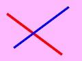
new 120 90
line red 3 10 20 90 80
line blue 2.5 100 10 20 70
background plum1
save linex.jpg
As we begin to populate InterDraw, it should be kept in mind that the interpreter is there to simplify matters; if instead of writing three lines of PHP, we only need to write one commando line, then its purpose is served. And in some cases we may be able to save much more than just two lines of PHP.
A grid is simply a set of vertical and horizontal lines that can easily be produced by starting with the example of the line above. A grid might come in handy for any number of applications (such as the internal grid of a graph, or in leveling and undistorting images). But it is also a good example for how one commando can be extended to produce multiple actions. The InterDraw syntax is grid color width spacing and its implementation is:
case "grid":
$draw = new LTImagickDraw ();
$draw->ColorWidthFill ($data[1], $data[2]);
for ($i = 1; $i < $height / $data[3]; $i++) $draw->line (0, $i * $data[3], $width, $i * $data[3]);
for ($i = 1; $i < $width / $data[3]; $i++) $draw->line ($i * $data[3], 0, $i * $data[3], $height);
$im->drawImage ($draw);
$draw->destroy ();
break;
new 120 90
grid orchid1 1 15
background chartreuse
save gridex.gif
ImagickDraw (and by inheritance, LTImagickDraw) will directly produce an ellipse if it is told to draw it from 0� to 360�. The InterDraw
syntax is
ellipse border_color border_width fill_color center_x center_y radius_horizontal radius_vertical
Since a circle is simply an ellipse with radius_horizontal = radius_vertical, I will not deal with Imagick's circle method here. This time, however,
we will also need to determine the fill colour, if we don't want an empty ellipse.
The ellipse is implemented:
case "ellipse":
$draw = new ImagickDraw ();
$draw->ColorWidthFill ($data[1], $data[2], $data[3]);
$draw->ellipse ($data[4], $data[5], $data[6], $data[7], 0, 360);
$im->drawImage ($draw);
$draw->destroy ();
break;
new 120 90
ellipse white 1 black 45 45 40 30
save ellipsex.gif
In addition to the features of having border and fill colours and a border width, any irregular polygon will consist of at least three pairs of
coordinates. Thus the basic Interdraw syntax will be
poly border_color border_width fill_color x1 y1 x2 y2 x3 y3 [{xn yn}]
Imagick will automatically join the last coordinate back to the first to seal the polygon. Some further points to note about the implementation of
the irregular polygon:
case "poly":
$draw = new LTImagickDraw ();
$draw->ColorWidthFill ($data[1], $data[2], $data[3]);
for ($i = 0; $i < (count ($data) - 4) / 2; $i++) $polydata[] = array ("x" => $data[(2 * $i + 4)], "y" => $data[(2 * $i + 5)]);
$draw->polygon ($polydata);
unset ($polydata);
$im->drawImage ($draw);
$draw->destroy ();
break;
new 120 90
poly white 1 black 45 45 40 85 110 80
poly lime 2 orange 110 65 100 5 10 20
poly none 0 cyan 5 25 40 45 35 85 10 80 15 45
background peachpuff
save polyex.gif
For regular polygons, on the other hand, it is not necessary to explicitly state the coordinates of the vertices, as they can be calculated from
knowing the number of sides, the centre point and the radius of the circle that would circumscribe the polygon. In addition to perfectly circular
polygons with a vertex at 0�, the regular polygons implemented here can be stretched in either the x- y-axis and rotated. The InterDraw syntax
thus contains some optional elements:
regpoly border_color border_width fill_color n_sides centre_x centre_y radius_horizontal [radius_vertical [rotate]]
This means that if we wish to rotate the polygon, its vertical radius will also have to be determined first.
However, if the polygon remains unrotated and unstretched, then the vertical radius can also be left out.
case "regpoly":
$draw = new LTImagickDraw ();
$draw->ColorWidthFill ($data[1], $data[2], $data[3]);
if (!isset ($data[8])) $data[8] = $data[7];
if (isset ($data[9])) $rotate = M_PI * $data[9] / 180; else $rotate = 0;
for ($i = 0; $i < $data[4]; $i++) $polydata[] = array ("x" => $data[5] + $data[7] * cos ($rotate + 2 * $i * M_PI / $data[4]), "y" => $data[6] + $data[8] * sin ($rotate + 2 * $i * M_PI / $data[4]));
$draw->polygon ($polydata);
unset ($polydata);
$im->drawImage ($draw);
$draw->destroy ();
break;
new 120 90
regpoly blue 2 greenyellow 5 45 45 40
regpoly black 3 none 5 75 50 40 40 -18
background tomato
save rpolyex.gif
The drawImage () function only has to be called once at the end of the switch and only if there is a $draw object:
if (isset ($draw))
{
$im->drawImage ($draw);
$draw->clear ();
$draw->destroy ();
unset ($draw);
}
Both clear () and destroy () will often be used in sequence for Imagick and ImagickDraw objects, and then, perhaps, for more than one object at a time. In this case it make sense to define a function to simplify the housekeeping:
function delete_images ($imagick_array)
{
if (!is_array ($imagick_array)) $imagick_array = array ($imagick_array);
foreach ($imagick_array as $imagick)
{
$imagick->clear ();
$imagick->destroy ();
}
}
And while we're at it, why not a function to dispose of temporary files that might also be produced on the way?
function delete_files ($files)
{
if (!is_array ($files)) $files = array ($files);
foreach ($files as $file) unlink ($file);
}
Then the above drawing action can be abbreviated to:
if (isset ($draw))
{
$im->drawImage ($draw);
delete_images ($draw);
unset ($draw);
}
If you plan on using the line function to draw complex graphs, then it is going a bit of a pain individually defining all of the line segments needed. In this case—and others are conceivable— why not put the data in a data line on its own and call the line function without any data on its own to render the line?
case "p:":
$points = array_shift ($data);
break;
Now for our line function to be able to use Imagick's polyline () function, this $points array has to be converted into a special array, where the keys to the x and y values are literally "x" and "y":
function convert_array_xy ($old_array)
{
$caxy = array ();
for ($i = 0; $i < count ($old_array) / 2; $i++)
if (isset ($old_array[2 * $i + 1])) $caxy[] = array ('x' => $old_array[2 * $i], 'y' => $old_array[2 * $i + 1]);
return $caxy;
}
Note the sanity check to prevent the function from failing: if the number of array elements is odd, then the last element will not be set with
just the x value.
The line function can look like this:
case "line":
$draw = new LTImagickDraw ();
checkdata (array ("black", 1, 1.0));
$draw->ColorWidthFill ($data[1], $data[2], "none", $data[3]);
$draw->setStrokeLineJoin (2);
$draw->polyline (convert_array_xy ($points));
break;
In this snippet of code note that we can now also set the line transparency, but that the fill colour is also transparent to prevent
polyline() from drawing a filled polygon. Also, the line joining mode has to be set; in most case the rounded joins
produced by the integer 2 are suitable.
This means that the irregular polygon can also use $points for its data:
case "poly":
$draw = new LTImagickDraw ();
checkdata (array ("black", 1, "none", 1.0));
$draw->ColorWidthFill ($data[1], $data[2], $data[3], $data[4]);
$draw->setStrokeLineJoin (2);
$draw->polygon (convert_array_xy ($points));
break;
Also the regpoly function can use $points that it must calculate before calling polygon ():
case "regpoly":
$draw = new LTImagickDraw ();
checkdata (array (0, 0, 0, 0, 0, 0, 0, $data[7], 0));
$draw->ColorWidthFill ($data[1], $data[2], $data[3]);
$draw->setStrokeLineJoin (2);
$rotate = deg2rad ($data[9]);
$points = array ();
for ($i = 0; $i < $data[4]; $i++) array_push ($points, $data[5] + $data[7] * cos ($rotate + 2 * $i * M_PI / $data[4]), $data[6] + $data[8] * sin ($rotate + 2 * $i * M_PI / $data[4]));
$draw->polygon (convert_array_xy ($points));
break;
Text is a little more complicated than the geometrical shapes in the last section. Both stroke colour and fill colour have to be defined. In
addition the font and the font size need to be defined; antialiasing the text would also be useful. Finally, text alignment and position have
to be determined.
In Imagick "text alignment" refers only to whether the text is left-justified, centred or right-justified; the point at which the
text is to be written has then to be calculated from a number of factors which depend on the font and its size.
The tasks at hand are:
case "text":
$draw = new ImagickDraw ();
$draw->ColorWidthFill ($data[1], 1, $data[3]);
$draw->setFontSize ($data[2]);
$draw->setFont ($data[4]);
$draw->setTextAntialias (true);
switch ($data[5])
{
case "right": $draw->setTextAlignment(Imagick::ALIGN_RIGHT); break;
case "left": $draw->setTextAlignment(Imagick::ALIGN_LEFT); break;
case "center": $draw->setTextAlignment(Imagick::ALIGN_CENTER); break;
}
for ($i = 0; $i < 8; $i++)
{
if ($i == 6) $adjustx = array_shift ($data);
elseif ($i == 7) $adjusty = array_shift ($data);
else array_shift ($data);
}
$text = html_entity_decode (implode ("\n", explode ("<br>", implode (" ", $data))), 0, "UTF-8");
$metrics = $im->queryFontMetrics ($draw, $text);
$adjustx = $data[6] * $width / 100;
$adjusty = $data[7] / 100 * ($height - $metrics["textHeight"] + $metrics["descender"]) + $metrics["characterHeight"];
$draw->annotation ($adjustx, $adjusty, $text);
break;
To determine which fonts (true-type only) are available on your machine, run the following:
<?php
$im = new Imagick ();
$fonts = $im->queryFonts ();
foreach ($fonts as $font) echo "$font<br>";
$im->destroy ();
?>
 new 120 90
text none 24 midnightblue Mary-Jane-deGroot center 52 -25 Now is<br>the time
background lightgoldenrod
save textex.gif
The scaling function presented here could be made much more sophisticated by allowing the full set of filter constants that Imagick supports.
However for most purely photographic manipulations the SINC filter is good enough. For the resize, three options are available: to a predetermined
pixel size of the width or height (with the aspect ratio conserved) or by a percentage. When resizing an image it is also customary to sharpen it
at the same time; the third optional parameter in the InterDraw code is the sharpening factor (< 1 for sharp; > 1 for blur; if unset then
it takes the value 1):
scale method value sharpen
The implementation is:
case "scale":
switch ($data[1])
{
case "w":
$width = $data[2];
$height = round ($width * $im->getImageHeight () / $im->getImageWidth ());
break;
case "h":
$height = $data[2];
$width = round ($height * $im->getImageWidth () / $im->getImageHeight ());
break;
case "%":
$width = round (($data[2] / 100) * $im->getImageWidth ());
$height = round ($width * $im->getImageHeight () / $im->getImageWidth ());
break;
}
if (!isset ($data[3])) $data[3] = 1;
$im->resizeImage ($width, $height, imagick::FILTER_SINC, $data[3]);
break;
And now for the grief. Blurry shadows and edges look really cool on photos, but their success depends on saving the file in a format that will allow partial transparency (normally only PNG and TIF) and, in some cases, transforming the file to a suitable format before doing any work on it. In adding a shadow we will need to:
case "shadow":
if (!isset ($data[4])) $data[4] = "ul";
switch ($data[4])
{
case "ul":
$x = 0;
$y = 0;
break;
case "ur":
$x = 4 * $data[3];
$y = 0;
break;
case "ll":
$x = 0;
$y = 4 * $data[3];
break;
case "lr":
$x = 4 * $data[3];
$y = 4 * $data[3];
break;
}
$shadow = $im->clone ();
$shadow->setImageBackgroundColor ($data[1]);
$shadow->shadowImage ($data[2], $data[3], 0, 0);
$shadow->compositeImage ($im, Imagick::COMPOSITE_OVER, $x, $y);
$im = $shadow->clone ();
delete_images ($shadow);
$width = $im->getImageWidth ();
$height = $im->getImageHeight ();
break;
Because shadowImage () always adds a border to the image depending on the value of extent, $width
and $height have to be reset.
The InterDraw commando runs:
shadow colour opacity_% extent [orientation]
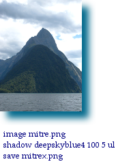
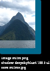
As can be seen from these examples, only PNG results in the correct image, both JPG and GIF are unusable. Because JPG interprets "transparent" as black, the font colour was changed to white for that example. GIF will still give an image with transparent areas, but it cannot interpret partial transparency. Interestingly, TIF produces an image that is almost identical to the JPG.
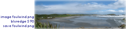
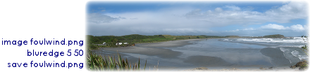
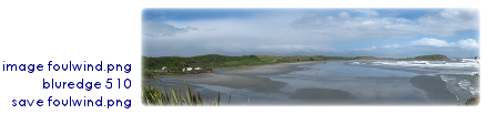
The idea with blurring the edges of a photos (also a cool effect) is to take an image, set and then blur its alpha channel and then
perform a gamma-shift (shift the midpoint of the blurred "grey") to eat up more or less of the remaining image. The only problem here
is that this "leveling" of the alpha channel cannot be performed by levelImage () from Imagick, so it has to
be accessed by executing convert at the command line.
Let's first have a look at what blurImage () can do on its own. By the way, this will also work for other blur methods
such as gaussianBlurImage (), although the Gaussian version takes a much longer time.
We need to:
 The result with
And the implementation thus far:
case "bluredge":
checkdata (5, 1, 0);
$im->setImageBackgroundColor ("none");
$im->setImageVirtualPixelMethod (imagick::VIRTUALPIXELMETHOD_TRANSPARENT);
$im->setImageMatte (true);
$im->blurImage (0, $data[1], imagick::CHANNEL_ALPHA);
Now, with blurImage () the edges are noticeably blurred but there are still distinct edges bounding the whole image. The method for blurring these sharp boundaries as well would be to transform the mask in such a way that more of the image belongs in the transparent part. Unfortunately here we have to revert to using the command line version for satisfactory results:
$im->writeImage ("temp0.png");
exec ("convert temp0.png -background none -virtual-pixel background -channel A -level 0,$data[2]% +channel temp1.png");
delete_images ($im);
$im = new Imagick ("temp1.png");
delete_files (array ("temp1.png", "temp0.png"));
break;
The InterDraw commando is now:
bluredge sigma extent
Note how as extent nears 0, more of the image is consumed by the blurred edge and, conversely, when the extent approaches 100,
the edges become more distinct.
There appears to be no way of doing this directly from the Imagick interface with the same results, but if anyone can show me, they'll get a
Mintie.
I have experimented with the following to replace the above five lines of code:
$im->levelImage (0, $data[2], 32767, imagick::CHANNEL_ALPHA);
but the resulting images differ considerably:
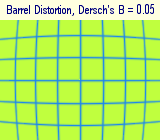
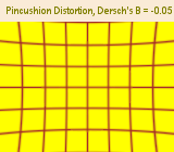 Imagick will do a number of distortions, many of which require some knowledge of what types and numbers of arguments need to be present in
order for the distortion to work. We will concentrate here on the barrel distortion, an optical distortion that often arises in cameras and needs
to be corrected for (but see also the following tutorial on a dedicated program that combines barrel with perspective
distortions to restore orthogonality, where I make the case that only Dersch's B is significant). In the meantime after further analysis it
appears that Dersch's A is also necessary, even though it is the wrong power (4th instead of 5th), because it at least can stand in for the
correct power at values of R ≈ 1. Dersch's D is dependent on the values of A and B (see "The Math" for further details directly
below). In any case, in the following code, the value for D is calculated from A and B for any aspect ratio.
Imagick will do a number of distortions, many of which require some knowledge of what types and numbers of arguments need to be present in
order for the distortion to work. We will concentrate here on the barrel distortion, an optical distortion that often arises in cameras and needs
to be corrected for (but see also the following tutorial on a dedicated program that combines barrel with perspective
distortions to restore orthogonality, where I make the case that only Dersch's B is significant). In the meantime after further analysis it
appears that Dersch's A is also necessary, even though it is the wrong power (4th instead of 5th), because it at least can stand in for the
correct power at values of R ≈ 1. Dersch's D is dependent on the values of A and B (see "The Math" for further details directly
below). In any case, in the following code, the value for D is calculated from A and B for any aspect ratio.
In this case, we will leave room for other types of distortion being determined in the second commando string and concentrate on the barrel distortion
case:
case "distort":
$aspect_ratio = max ($width / $height, $height / $width);
$da = $data[2];
$db = $data[3];
switch ($data[1])
{
case "barrel":
$cnst = imagick::DISTORTION_BARREL;
if (isset ($data[4])) $dd = $data[4]; else
{
if ($db + $da > 0) $dd = 1 - $db * (1 + pow ($aspect_ratio, 2)) - $da * pow (1 + pow ($aspect_ratio, 2), 1.5);
else $dd = min (1 - $db * pow ($aspect_ratio, 2) - $da * pow ($aspect_ratio, 3), 1 - $db - $da);
}
break;
}
$im->setImageVirtualPixelMethod (imagick::VIRTUALPIXELMETHOD_TRANSPARENT);
$im->distortImage ($cnst, array ($da, $db, 0, $dd), true);
break;
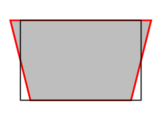
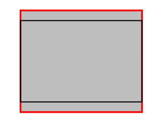
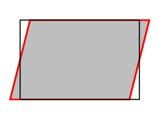
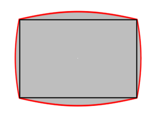
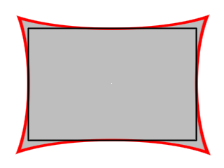
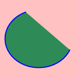
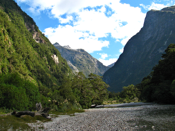
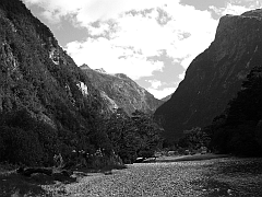
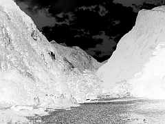
In order to save as much of the image as possible without "blank" areas arising (which would be filled in, in any case, with the
virtual pixel method), it is necessary to keep the length of the blue lines in the following cases constant. The saved and original images
are shown in very light grey, and the amount lost in the transformation in darker grey:
 In the barrel distortion case (to counteract a lens pincushion distortion, A + B > 0), the diagonal R has to transform to itself under the Dersch equation:
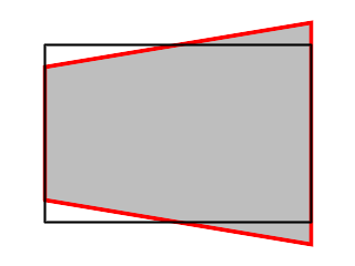
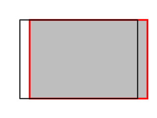
 In the pincushion distortion case (to counteract a lens barrel distortion, A + B ≤ 0), however, the x and y distortions have to be considered separately.
For the y distortion in the landscape orientation, this means that:
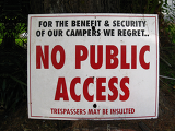 |
image public_lt.png # distort barrel 0.0173 -0.04744 scale w 160 0.8 save public_or.png |
image public_lt.png distort barrel 0.0173 -0.04744 scale p 160 0.8 save publicex.png |
 |
Quite a number of image transformations affect the image as a whole and require few parameters. Even then, some parameters that
Imagick requires seem to have no effect. In this case they can usually be set to a value known to work and the operator can be left to
manipulate values that will make a difference.
Before launching into this, let me introduce one further function, in addition to checkdata (), which will come in
handy when dealing with these transformations. This function translates a string into the corresponding Imagick::CHANNEL_
constant, by directly setting it to the appropriate integer (and thanks again to the Imagick team for all that information about what integers are):
function find_channel ($cnst)
{
switch ($cnst)
{
case "red" : $cnst = 1; break;
case "gray" : $cnst = 2; break;
case "cyan" : $cnst = 3; break;
case "green" : $cnst = 4; break;
case "magenta" : $cnst = 5; break;
case "blue" : $cnst = 6; break;
case "yellow" : $cnst = 7; break;
case "alpha" : $cnst = 8; break;
case "opacity" : $cnst = 9; break;
case "matte" : $cnst = 10; break;
case "black" : $cnst = 11; break;
case "index" : $cnst = 12; break;
case "all" : $cnst = 13; break;
case "default" : $cnst = 14; break;
default: $cnst = 0;
}
return $cnst;
}
The rest, as they say, is history:
case "oilpaint":
checkdata (0);
$im->oilPaintImage ($data[1]);
break;
case "vignette":
checkdata (array (0, 0));
$im->vignetteImage ($data[1], $data[2], 0, 0);
break;
case "despeckle":
$im->despeckleImage ();
break;
case "charcoal":
checkdata (array (0, 0));
$im->charcoalImage ($data[1], $data[2]);
break;
case "emboss":
checkdata (array (0, 0));
$im->embossImage ($data[1], $data[2]);
break;
case "solar":
checkdata (0);
$im->solarizeImage (pow (2, 12 + $data[1]));
break;
case "sketch":
checkdata (array (0, 0));
$im->sketchImage (0, $data[1], $data[2]);
break;
case "sigmoid":
checkdata (array (0, 0));
$im->sigmoidalContrastImage (true, $data[1], $data[2]);
break;
case "contrast":
checkdata (0);
if ($data[1] > 0) for ($i = 0; $i < $data[1]; $i++) $im->contrastImage (true);
else for ($i = 0; $i > $data[1]; $i--) $im->contrastImage (false);
break;
case "sepia":
checkdata (0);
$im->sepiaToneImage ($data[1]);
break;
case "equal":
$im->equalizeImage ();
break;
case "normal":
checkdata ("all");
$channel = find_channel ($data[1]);
$im->normalizeImage ($channel);
break;
case "negate":
checkdata ("all");
$channel = find_channel ($data[1]);
$im->negateImage (false, $channel);
break;
case "poster":
checkdata (0);
$im->posterizeImage ($data[1], false);
break;
case "channel":
checkdata ("red");
$im->separateImageChannel ($data[1]);
break;
case "tint":
checkdata ("red");
$im->tintImage ($data[1], 1);
break;
case "gamma":
checkdata (array (1.0, "all"));
$channel = find_channel ($data[2]);
$im->gammaImage ($data[1], $channel);
break;
| ImageMagick | InterDraw | ImageMagick | InterDraw |
|---|---|---|---|
| oilPaintImage (radius) | oilpaint radius | charcoalImage (radius, sigma) | charcoal radius sigma |
| vignetteImage (blackpoint, whitepoint, centerX, centerY) | vignette blackpoint whitepoint | despeckleImage (void) | despeckle |
| embossImage (radius, sigma) | emboss radius sigma | solarizeImage (threshold) | solar threshold |
| sketchImage (radius, sigma, angle) | sketch sigma angle | sigmoidalContrastImage (direction, amount, midpoint) | sigmoid amount |
| sepiaToneImage (threshold) | sepia threshold | equalizeImage (void) | equal |
| normalizeImage (channel) | normal channel | negateImage (gray, channel) | negate channel |
| posterizeImage (levels, dither) | poster levels | separateImageChannel (channel) | channel index |
| tintImage (tint, opacity) | tint color | gammaImage (gamma, channel) | gamma gamma channel |
Now let's give Mel the Andy Warhol treatment and see what she comes out looking like:
Before some misguided soul decides to spend the remainder of their life translating all the other arcane functions that Imagick has to offer into InterDraw drawing codes, let's reflect a minute about on what InterDraw is intended to achieve: Not simplicity in its own right, but the rendering of Utilitarian Concepts. Simplicity on its own can be readily achieved by simplifying the function names, leaving off parameters that have no effect, etc. This much has become obvious from the treatment of the photographic transformations in the last section. But the idea of Utilitarian Concepts requires that something awfully complicated in PHP code can be reduced to a small number of almost intuitive parameters without losing any of the necessary detail. It is thus we turn to the problem of drawing a pie chart.

The classical implementation of the pie chart in PHP's GD graphics is to stack a series of elliptical sectors onto one another. This approach fails at the outset with Imagick because the functions ellipse () and arc (), which are in reality synonyms, do not result in sectors, but in curiously closed arcs, segments. Give those guys a dictionary.
In order to draw a true sector, we require:
case "sector":
$draw = new LTImagickDraw ();
checkdata (array ("blue", 1, "red", 10, 10, 10, 10, 0, 90));
list (, $l_color, $l_width, $f_color, $cx, $cy, $rw, $rh, $s_deg, $f_deg) = $data;
#[more on setting the darker colour $dark_color here later]
$dark_color = $f_color; # for the time being
$draw->ColorWidthFill ("none", 0, $dark_color);
$start = deg2rad ($s_deg);
$finish = deg2rad ($f_deg);
#[start of ellipse drawing looop - see later]
$points = array ($cx, $cy);
if ($f_deg - $s_deg > 180)
{
$draw->ellipse ($cx, $cy, $rw, $rh, $s_deg, $s_deg + 180);
$draw->ellipse ($cx, $cy, $rw, $rh, $s_deg + 180, $f_deg);
array_push ($points, $cx + $rw * cos ($start + M_PI), $cy + $rh * sin ($start + M_PI));
} else
{
$draw->ellipse ($cx, $cy, $rw, $rh, $s_deg, $f_deg);
array_push ($points, $cx + $rw * cos ($start), $cy + $rh * sin ($start));
}
array_push ($points, $cx + $rw * cos ($finish), $cy + $rh * sin ($finish));
$draw->polyline (convert_array_xy ($points));
#[more on 3-D sectors here later]
break;

The InterDraw code and its result are:
new 160 120
sector deepskyblue 2 deepskyblue4 82 65 75 50 0 130
sector violetred 2 violetred4 78 55 75 50 130 360
background tan
If a tenth parameter were introduced this could be the height of the pie. A missing tenth parameter could be checked for and set to 1; then we could loop through drawing the ellipses, raising them one pixel at a time:
#[first check for ten parameters]
checkdata (array ("blue", 1, "red", 10, 10, 10, 10, 0, 90, 1));
list (, $l_color, $l_width, $f_color, $cx, $cy, $rw, $rh, $s_deg, $f_deg, $hgt) = $data;
#[and now the loop]
for ($i = 0; $i < $hgt; $i++)
{
$ncy = $cy - $i;
$points = array ($cx, $ncy);
if ($f_deg - $s_deg > 180)
{
$draw->ellipse ($cx, $ncy, $rw, $rh, $s_deg, $s_deg + 180);
$draw->ellipse ($cx, $ncy, $rw, $rh, $s_deg + 180, $f_deg);
array_push ($points, $cx + $rw * cos ($start + M_PI), $ncy + $rh * sin ($start + M_PI));
} else
{
$draw->ellipse ($cx, $ncy, $rw, $rh, $s_deg, $f_deg);
array_push ($points, $cx + $rw * cos ($start), $ncy + $rh * sin ($start));
}
array_push ($points, $cx + $rw * cos ($finish), $ncy + $rh * sin ($finish));
$draw->polyline (convert_array_xy ($points));
}

The InterDraw code and its result now look like this (changes highlighted in red):
new 160 120
sector deepskyblue 2 deepskyblue4 82 65 75 50 0 130 10
sector violetred 2 violetred4 78 52 75 50 130 360
background tan
The 3-D pie chart could do with at least two improvements:
What say we darken the original colour by reducing its RGB values to 75% of what they are, draw (n - 1) sectors in that colour with the nth sector in the desired colour. There are at least five ways of determining the individual RGB values:
function brightness ($cstring, $amount)
{
$amount = min (100, $amount);
$amount = max (-100, $amount);
$cl = new ImagickPixel ($cstring);
$carray = $cl->getColor ();
if ($amount > 0) $red = round ($carray["r"] + $amount * (255 - $carray["r"]) / 100); else $red = round ($carray["r"] * (1 + $amount / 100));
if ($amount > 0) $green = round ($carray["g"] + $amount * (255 - $carray["g"]) / 100); else $green = round ($carray["g"] * (1 + $amount / 100));
if ($amount > 0) $blue = round ($carray["b"] + $amount * (255 - $carray["b"]) / 100); else $blue = round ($carray["b"] * (1 + $amount / 100));
$clv = "rgb($red,$green,$blue)";
delete_images ($cl);
return $clv;
}
Now the variable $dark_color can be set when initialising the values:
$dark_color = brightness ($f_color, -25);
And the following line can be inserted at the beginning of the stacking loop:
if ($i == $data[10] - 1) $draw->setFillColor ($f_color);

Our InterDraw code and its result now look like this:
new 160 130
sector deepskyblue 2 deepskyblue4 82 75 75 50 0 130 10
sector violetred 2 violetred4 78 62 75 50 130 360 10
background tan
To top it all off, we'll add some outlines to enhance the effect. Before going about drawing the lines, the stroke colour has to be set to the
value present in the posted data, as does the stroke width, and the fill colour has to be set to transparent:
$draw->ColorWidthFill ($l_color, $l_width, "transparent");
Then the lines in order:
#[1]
$draw->ellipse ($cx, $ncy, $rw, $rh, $s_deg, $f_deg);
#[2]
if ($s_deg < 180) $draw->ellipse ($cx, $cy, $rw, $rh, max ($s_deg, 0), min ($f_deg, 180));
elseif ($f_deg > 360) $draw->ellipse ($cx, $cy, $rw, $rh, 0, $f_deg % 360);
#[3]
if ($s_deg > 90 and $s_deg < 270) $draw->line ($cx, $cy, $cx + $rw * cos ($start), $cy + $rh * sin ($start));
if ($f_deg < 90 or ($f_deg > 270 and $f_deg < 450)) $draw->line ($cx, $cy, $cx + $rw * cos ($finish), $cy + $rh * sin ($finish));
#[4]
$draw->polyline (convert_array_xy (array ($cx + $rw * cos ($finish), $ncy + $rh * sin ($finish), $cx, $ncy, $cx + $rw * cos ($start), $ncy + $rh * sin ($start))));
if (($s_deg < 90 and $f_deg < 90) or ($s_deg > 90 and $f_deg > 90 and $f_deg < 450)) $draw->line ($cx, $cy, $cx, $ncy);
#[5]
if ($s_deg < 270 and $s_deg > 0) $draw->line ($cx + $rw * cos ($start), $ncy + $rh * sin ($start), $cx + $rw * cos ($start), $cy + $rh * sin ($start));
elseif (($s_deg < 0 and $f_deg > 0) or ($s_deg < 360 and $f_deg > 360)) $draw->line ($cx + $rw, $cy, $cx + $rw, $ncy);
if ($f_deg < 180 or $f_deg > 270) $draw->line ($cx + $rw * cos ($finish), $ncy + $rh * sin ($finish), $cx + $rw * cos ($finish), $cy + $rh * sin ($finish));
elseif ($s_deg < 180 and $f_deg > 180) $draw->line ($cx - $rw, $cy, $cx - $rw, $ncy);
The same InterDraw code from above sequentially draws:
| 1 | 2 | 3 | 4 | 5 |
|---|---|---|---|---|
 |
 |
 |
 |
 |
When all put together the sector part of InterDraw takes up more than 50 lines of code, yet is accessed by no more
than 10 pieces of data. That, to me, is the power of a Utilitarian Concept. We can argue about the aesthetics, but crunching 50 lines of code
down into one is the effect I'm looking for, not the bean-counting of getting all the Imagick functions to work with InterDraw. Possible future
functions might include: plotting graphs from data file or databases, with automatic recognition of x and y axis ranges; or corporate-identity
data-graphing with custom graphic placements and colours. A better "perspective" pie graph might actually use the perspective
transformation that Imagick offers, rather than the very simplified version I have described. Or reduce aliasing by producing a larger graphic
and then scaling it down. Anything to make life simpler and more pleasing, and anything rather than Microsoft!
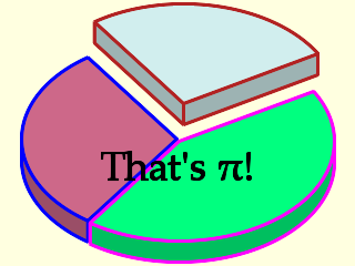
The code that gives us "That's π!" from the top of the page is astoundingly simple:
new 320 240
sector blue 2.5 palevioletred3 159 144 140 90 125 235 20
sector magenta 2.5 springgreen 161 146 140 90 330 485 20
sector firebrick 2.5 lightcyan2 165 112 140 90 235 330 20
text black 36 black Palatino-Linotype center 50 70 That's π!
background lightyellow1
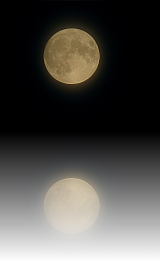
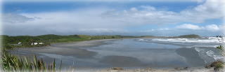
Table surface reflections—where an image is reflected in a surface and becomes less distinct in both focus and strength as the reflection deepens—are currently en vogue and ImageMagick is a way of achieving them. However, we do have to resort to the command line here (at least in PHP use the exec () function) because the Imagick functions prove to be not quite up to the challenge.
Briefly the steps in produce the reflect/blur functions are:
case "reflect-blur":
checkdata (array (100, 0, 10));
$im_temp = $im->clone ();
$im_temp->flipImage ();
$im_temp->writeImage ("sharp.png");
$im_temp->blurImage (0, $data[3]);
$im_temp->writeImage ("blur.png");
$mask = new Imagick ();
$mask->newPseudoImage ($width, $height, "gradient:black-white");
$mask->writeImage ("mask.png");
exec ("composite blur.png sharp.png mask.png -compose srcover temp.png");
$im_temp = new Imagick ("temp.png");
$mask->newPseudoImage ($width, $height, "gradient:gray{$data[1]}-gray{$data[2]}");
$im_temp->compositeImage ($mask, imagick::COMPOSITE_COPYOPACITY, 0, 0);
$im->addImage ($im_temp);
delete_images (array ($mask, $im_temp));
delete_files (array ("sharp.png", "blur.png", "temp.png", "mask.png"));
$im->resetIterator ();
$im = $im->appendImages (true);
$height = $height * 2;
break;
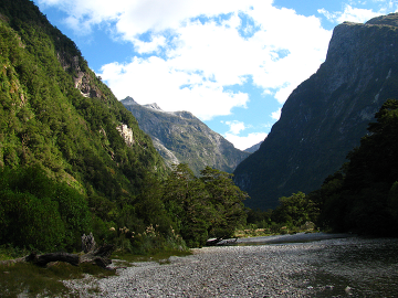
A further popular image manipulation is Advanced Tone Mapping (ATM)—in particular on High Dynamic Range (HDR) images. These are images formed from bracketed series (e.g. from under- to overexposed individual images) in order to extend the dynamic range of the digital camera sensor. ATM is then applied as the icing on the cake to enhance local contrast; but it can also be used on normal images as well, as in the example below.
GIMP has an ATM plug-in script available here and from the source it was possible to construct an ImageMagick equivalent. First, let's consider what the GIMP script achieves:
case "atm":
checkdata (array (5, 75, 90, 1));
$im_temp = $im->clone ();
$im->addImage ($im);
$im->modulateImage (100, 0, 100);
$im->negateImage (true);
$radius = round ($data[1] * ($width + $height) / 200);
$im->gaussianBlurImage ($radius, $radius / 3.1);
$im->setImageMatte (true);
$im->setImageOpacity ($data[2] / 100);
$im = $im->flattenImages ();
$im->setImageMatte (true);
$im->setImageOpacity ($data[3] / 100);
for ($i = 0; $i < $data[4]; $i++) $im_temp->compositeImage ($im, imagick::COMPOSITE_SOFTLIGHT, 0, 0);
$im = $im_temp->clone ();
break;
But even this doesn't give the exact image that GIMP does. For one thing, the blurring seems to take ages and the blur is executed differently by the two programs—GIMP appears not to need a $sigma value for the blur and the effects were similar when I set the divisor to 3.1; π or √10 were both too large and 3.0 was too small.
In any case here is a series of images to compare:
 | 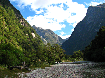 |  |
| Original | GIMP | ImageMagick |
|---|
The Imagick image is somewhat brighter than the GIMP version, especially in the darker areas and in my opinion this is what Advanced
Tone Mapping is meant to achieve. I can only suppose that Imagick's SOFTLIGHT procedure differs from that of the GIMP. The Interdraw syntax:
atm blur_% float blur_opacity_% float merge_opacity_% float copies int
For comparison here are the intermediate stages of both programs. The modulateImage () function performs exactly the same as desaturation by light values in the GIMP; negation is identical; then small differences start appearing with the blur and the initial merge. Top row is Imagick, bottom is GIMP:
 |  |  |  |
 |  |  |  |
| Desaturation | Negation | Blur | Flatten |
|---|
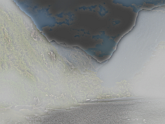
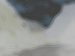
 |  |
| Excerpt (upper left corner, 100%) with chromatic aberration | Chromatic aberration removed |
|---|
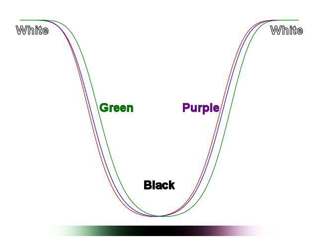
Chromatic aberration is difficult to deal with in a "one size fits all" approach, because it involves a number of separate phenomena (see Walree for more details). Here I propose a method for reducing the type of chromatic aberration that results from the mismatch in size between the different colour channels. In the original above, a cross-section of the leading green edge of the black line reveals the following spectral shifts:
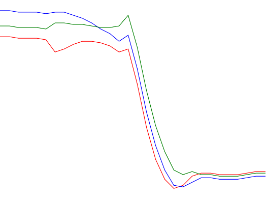
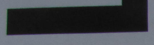
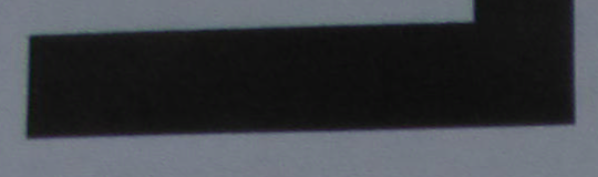
For the picture to have all only black or white pixels, both the red and the blue lines would have to be shifted a couple of pixels to the right, so that they would overlay the green line. The purple coloration on the following edge of the black line is due to the lagging of the green channel as it enters the white area. The image under the data sample shows the effects of exaggerating this kind of chromatic aberration on a black line on a white background.
Let us assume that transverse or lateral chromatic aberration increases linearly from the centre of the image to the periphery and attempt to measure the amount of aberration. Ideally a photograph of a black right angle near the corner of the picture would provide a number of cross sectional samples needed to measure the channel shifts at their greatest. However, since we would be using only vertical or horizontal samples, and what we need to measure is the vector by which the corner of the image channel has to be displaced, our measured vertical or horizontal displacement has to be multiplied by a factor of (diagonal distance from centre) / (vertical distance from midline) for the vertical displacement (substitute horizontal distance from midline when calculating the horizontal displacement). Furthermore, we would like to measure the vector directly at the corner of the picture, but our measurements will only be more or less near the corner, so they have to be multiplied again by (picture diagonal) / (diagonal distance from centre). Taking these two factors together, we are left with multiplying the measured channel shift by (picture diagonal) / (vertical distance from midline) or (picture diagonal) / (horizontal distance from midline) as the case may be, giving in both cases the length of the corner vector.
This corner vector will have the same direction of the diagonal; so that the x-displacement will be 0.8 of the total, and the y-displacement 0.6 of the total, in a 4:3 image in landscape orientation. In the case of the example given above with its green leading and purple trailing edges as we move towards the centre, both the red and the blue channels will have to be shrunk to make them match the green channel.
The unit of displacement is absolute, i.e. in pixels. This is important when adjusting the displacement to differently sized images.
Furthermore, the measured chromatic aberration can be quite variable from image to image, and it is most noticeably dependent on the aperture, so that many different measurements have to be made to determine the channel shifts with any degree of reliability.
For the above image, the red displacement was measured at 1.658 � 0.776 pixels and the blue at 2.235 � 1.064 pixels for f = 8.0. Since these values were determined by several hundred measurements, the large variation need not be of great concern. What has to be achieved now is that all four corners of the red channel have to be shifted by 1.658 pixels towards the center, likewise the corners of the blue channel by 2.235 pixels. We'll pass those parameters as red_shift and blue_shift in the Interdraw data:
case "chroma":
checkdata (array (0, 0));
$diagonal = sqrt (pow ($width, 2) + pow ($height, 2));
$x = $width / $diagonal;
$y = $height / $diagonal;
$red_ca_x = $x * $data[1];
$red_ca_y = $y * $data[1];
$blue_ca_x = $x * $data[2];
$blue_ca_y = $y * $data[2];
$transform_red = array (0, 0, $red_ca_x, $red_ca_y, 0, $height, $red_ca_x, $height - $red_ca_y, $width, $height, $width - $red_ca_x, $height - $red_ca_y, $width, 0, $width - $red_ca_x, $red_ca_y);
$transform_blue = array (0, 0, $blue_ca_x, $blue_ca_y, 0, $height, $blue_ca_x, $height - $blue_ca_y, $width, $height, $width - $blue_ca_x, $height - $blue_ca_y, $width, 0, $width - $blue_ca_x, $blue_ca_y);
$red = clone $im;
$red->separateImageChannel (imagick::CHANNEL_RED);
$red->setImageVirtualPixelMethod (imagick::VIRTUALPIXELMETHOD_EDGE);
$red->distortImage (imagick::DISTORTION_PERSPECTIVE, $transform_red, false);
$green = clone $im;
$green->separateImageChannel (imagick::CHANNEL_GREEN);
$red->addImage ($green);
$blue = clone $im;
$blue->separateImageChannel (imagick::CHANNEL_BLUE);
$blue->setImageVirtualPixelMethod (imagick::VIRTUALPIXELMETHOD_EDGE);
$blue->distortImage (imagick::DISTORTION_PERSPECTIVE, $transform_blue, false);
$red->addImage ($blue);
$red->setFirstIterator ();
$im = $red->combineImages (imagick::CHANNEL_ALL);
delete_images (array ($red, $green, $blue));
break;
A complete operating version of all the functions so far described can be downloaded here.
addimage x_offset float y_offset float file_name string
atm blur_% float blur_opacity_% float merge_opacity_% float copies int
background colour color
bluredge sigma float extent% float
channel index int
charcoal radius int sigma int
chroma red_shift float blue_shift float
despeckle
distort method "barrel" value_a float value_b float [value_d float]
ellipse border_colour color border_width float fill_colour color center_x float center_y float radius_horizontal float radius_vertical float
emboss radius int sigma int
equal channel channel
gamma gamma float channel channel
grid colour color width float spacing float
image file_name string
line colour color width float [transparency float]
negate channel channel
new width int height int [background_colour color]
normal channel channel
oilpaint radius int
p: x1 float y1 float x2 float y2 float [{xn float yn float}]
poly border_colour color border_width float fill_colour color line_transparency float
poster levels int
reflect-blur opacity%_top int opacity%_bottom int blur_pixel_radius float
regpoly border_colour color border_width float fill_colour color n_sides int center_x float center_y float radius_horizontal float [radius_vertical float [rotate float]]
save file_name string
scale method "w|h|%" value float [sharpen float]
sector border_colour color border_width float fill_colour color center_x float center_y float radius_horizontal float radius_vertical float angle_begin float angle_end float [layers int]
sepia threshold int
shadow colour color opacity_% float extent float [orientation "ul|ur|ll|lr"]
sigmoid amount float
sketch sigma int angle float
solar threshold int
text outer_colour color font_size float font_colour color font string justify "center|left|right" adjust_x float adjust_y float output html string
tint tint color
vignette blackpoint int whitepoint int
Notes:
ImageMagick has a wide potential for image manipulation and only the basic outlines are given here. Any number of additions to InterDraw or optimisation or extension of its methods can be imagined. For the exercises, however, I have chosen two particularly promising extensions.
The photographic manipulations all checked for the right number of parameters and set missing parameters to default values by accessing the
global variable $data. Task: Extend the error checking to other kinds of parameters and rewrite these to
$dcode, which would be displayed in the drawing code box in the corrected form when the drawing is executed.
Hint: In the original code I simply turned $dcode into an array of the same name and instructed the code to work
through $dcode member (i.e. line) by member, because I had no further use for it. But if the array were called
$dcode_array, then $dcode could be unset and progressively added to as each line is drawn.
The next obvious stage of development would be to have InterDraw produce whole sequences of images with the intention of either experimenting with small changes to large numbers of images for optimisation or producing animations. Tasks: