

Contents |
||
| Previous Tutorial | Back to Index | Next Tutorial |
|---|
|
Lens aberration ⇒ | |
Software? ⇔ | |
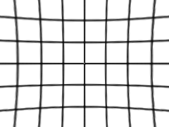
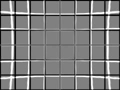
Spherical lens distortions (Seidel Aberrations) are present on nearly all images taken by conventional and digital cameras, resulting usually in an enlargement of the centre of an image in respect to the periphery ("barrel effect") or a reduction in the image size at the centre ("pincushion effect"). For a number of purposes it would be useful if the images could be made "flat" by software manipulation, e.g. prior to stitching photos into panoramas or for taking photos for architectural or artistic purposes.
I have already demonstrated in the previous tutorial how ImageMagick's imageDistort () can be used to help orthogonalise photos (i.e. to render shapes rectangular that are, in reality, rectangles), but this assumes that the Dersch coefficients for a particular lens or camera are known before performing the manipulation. Suitable images that have been taken with a particular lens or camera can be used to infer the Dersch coefficients, and thus be in a position to do two types of manipulation:
The topic of installing Imagemagick® and the Imagick DLL for PHP on your computer has been dealt with in the tutorial on ImageMagick® and Panorama Processing.
Strictly speaking, ImageMagick is not required for calculating the Dersch coefficients, nor is it essential for doing the simple image manipulations required for levelling the image and obtaining the coordinates of line points which are the necessary input for calculating the coefficients. Alternative code for GD (which is packaged with PHP) is given below.
The Dersch equation is an attempt to describe how a point at radius R behaves under the Seidel Aberration:
Ar4 + Br3 + Cr2 + Dr = R, or
r * (Ar3 + Br2 + Cr + D) = R
where R is the source radius (i.e. the radius of the original image) and r the destination radius.
This is problematic on its own because the Dersch equation actually reverses the source and the destination. The author of
IMATEST says as much, but presents their own equation is essentially the
form used by Dersch (where the undistorted radius ru is a single term on one side of the equation and the distorted radius
rd appears in polynomial form on the other). Van Walree has
the correct equations.
Since we can only really know the source or undistorted radii (either we have taken the perfect picture of a chequer board, or we have a photo that requires undistorting) we are left with having to solve the Dersch equation for four unknowns.
A second problem here is that the coefficients A and C are optically meaningless and could just as well be set to 0. A fifth power term, which could have been coded for in graphics manipulations, is not present. (Aberrations which require a fifth power term to be described or reversed may cause straight lines to have a "moustache" form, convexly curved in the middle, concavely curved towards the edges.)
The third problem—and this is where the trouble begins—is then that the Dersch equation is used as the basis for the distortions within ImageMagick to reverse the Seidel Aberration. It is a trivial matter to set the coefficient C to 0 always; but the fourth power coefficient A has to stand in for a genuine fifth power term. This may not mean much deviation from an optimal solution in practical terms, as the term R can only have a maximum value dependent on the aspect ratio of the image (5/3 for classical images, 18.357.../9 for wide screen images), and the coefficient for a fifth power term is generally much smaller than that for the third power term. But annoying, nonetheless.
The real trouble is when the makers of ImageMagick reveal that they have no idea where the journey is heading and provide two types of poorly named distortions: Imagick::DISTORTION_BARREL and Imagick::DISTORTION_BARRELINVERSE, and there is widespread confusion about what these distortions actually accomplish. By reverse engineering the Imagick distortions we will see that, indeed, the erroneous equations of Dersch and others are applied by Imagick, and this will give us an inkling of how these distortions might be applied to reverse or indeed imitate the Seidel Aberration.
First and foremost, it is important to note that the Imagick::DISTORTION_BARRELINVERSE constant does not
"undo" a distortion performed with the Imagick::DISTORTION_BARREL constant; it simply uses another, although
equally erroneous, equation for calculating distortion:
r / (Ar3 + Br2 + Cr + D) = R
with R and r being the source and destination radii respectively, as above. Instead of using the ambiguous and
misleading terms barrel and inverse barrel, I propose multiplicative and divisive transformations.
Let us begin by generating a couple of distortions with InterDraw using both constants. The InterDraw code for the first image is:
new 320 240 none
grid black 2 20
distort barrel 0.06 -0.18 1
background white
By introducing the parameter ibarrel in the distort function, the
Imagick::DISTORTION_BARRELINVERSE constant is applied; also the fifth parameter set to 1 ensures that the coefficient
d = 1, rather than to a factor which would scale the image to fit the dimensions given. In all cases,
c = 0.
| Description | InterDraw Distortion | Reverse Engineered Distortion | Differential Image with grain extraxt |
|---|---|---|---|
| Multiplicative Transformation, with a = 0.06, b = -0.18 |  |
 |
 |
| Multiplicative Transformation, with a = -0.06, b = 0.18 | 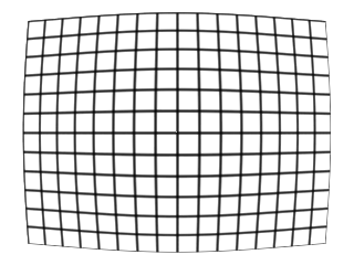 |
 |
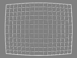 |
| Divisive Transformation, with a = 0.06, b = -0.18 |  |
 |
 |
| Divisive Transformation, with a = -0.06, b = 0.18 |  |
 |
 |
The results obtained are quite respectable, since the reverse engineering involved taking the intersection points of the grid, transforming them, and then joining them with lines of fixed width, so that minor differences in line width due to line curvature in the raw distortions arise. The raw distortions also result in the lines becoming thicker in pincushion and thinner in barrel distortions and this accounts for the edges in the grain extract comparisons. Apart from that, no essential differences in curvature are observable. The code for the reverse engineering can be found here.
How to solve the Dersch equations for r, which is in polynomial form? The fastest method is by iteration, which I will take a little
time to explain, as we will be using this method extensively later, and we will need to understand why the equations used appear to be the opposite
of what they should be.
In summary, we know the source value R and we wish to calculate the destination value r which it will map to.
The only thing we need to know is that both source and destination values will be in the same ball park, so let's see what happens if we plug our
source value into the equation where the destination value should be:
| Dersch's a | 0.06 |
| Dersch's b | -0.18 |
| Rsrc (target) | 1.2 |
| Iterative solutions | |
|---|---|
| Rdest | Rsrc |
| 1.2 | 1.013376 |
What we now have is a solution for Rsrc = R =1.013376, namely Rdest = r = 1.2. What say we now proportionally increase r by the amount that our solution falls behind 1.2? We need to multiply the 1.2, which is our target, by the 1.2 we started with and divide by the value our equation spat out and then calculate what value this would lead to:
| Rdest | Rsrc |
|---|---|
| 1.2 | 1.013376 |
| 1.4209928 | 1.149154283 |
| =1.2*1.2/1.013376 | =0.06*1.42099284-0.18*1.42099283+1.4209928 |
We haven't yet reached the value we are aiming for, but we are much closer. After several more iterations:
| Rdest | Rsrc |
|---|---|
| 1.2 | 1.013376 |
| 1.4209928 | 1.149154283 |
| 1.483866341 | 1.186649721 |
| =1.2*1.4209928/1.149154283 | =0.06*1.4838663414-0.18*1.4838663413+1.483866341 |
| 1.500560424 | 1.196583453 |
| 1.504844903 | 1.199132738 |
| 1.505933269 | 1.199780333 |
| 1.50620899 | 1.199944392 |
| 1.506278791 | 1.199985925 |
| 1.506296458 | 1.199996438 |
| 1.50630093 | 1.199999098 |
| 1.506302062 | 1.199999772 |
| 1.506302348 | 1.199999942 |
| 1.506302421 | 1.199999985 |
| 1.506302439 | 1.199999996 |
| 1.506302444 | 1.199999999 |
| 1.506302445 | 1.2 |
Eventually a point is reached where the differences between the values for Rdest fluctuate so minimally, that we can take that value as-near-as-dammit, or the values converge to a single value. Now we know that a point at source radius 1.2 will map to destination radius 1.506302445. Note the lines in the tables in blue, which detail the calculation involved at arriving at the values in the line above in the table. This type of calculation can be done in e.g. Excel where care has to be taken to distinguish between relative references (i.e. to "the value in the cell above") and absolute references (i.e. to "the value in a particular cell"): In the case above, "1.2", "0.06" and "-0.18" represent absolute references, whereas the other values are relative references.
Putting this into math, we are iteratively calculating a new R'dest by multiplying the target Rsrc by the old Rdest and dividing by the old Rsrc, which in turn was calculated by inserting the old Rdest values into the Dersch equation:
| R'dest = | Rsrc * Rdest | , where C = 0 and D = 1. |
| Rdest * (A * Rdest3 + B * Rdest2 + 1) |
| R'dest = | Rsrc * | = | Rsrc |
| A * Rdest3 + B * Rdest2 + 1 |
$limit = 0.0000001;
# $rl is calculated as the radius of the intersection points of the grid, i.e. the source radius
$dest = $rl;
do
{
$dest_old = $dest;
$dest = $rl / ($da * pow ($dest, 3) + $db * pow ($dest, 2) + 1);
} while (abs ($dest - $dest_old) > $limit);
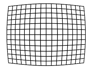
With InterDraw, it is possible to produce grid and line images and apply imageDistort () with its correspondent constants in any sequence and at any desired resolution. First, let's see what happens when we first apply an Imagick::DISTORTION_BARREL distortion and try to reverse it by applying the Imagick::DISTORTION_BARRELINVERSE distortion and vice versa. The visual effect:
|
 |
 |
 |
| Original | new 240 180 grid black 2 29.9 distort barrel 0.06 -0.18 1 background white |
new 240 180 grid black 2 29.9 distort barrel 0.06 -0.18 1 distort ibarrel 0.06 -0.18 1 background white |
Original compared with final image by grain extract |
|---|---|---|---|
 |
 |
 |
|
|
new 240 180 grid black 2 29.9 distort ibarrel 0.06 -0.18 1 background white |
new 240 180 grid black 2 29.9 distort ibarrel 0.06 -0.18 1 distort barrel 0.06 -0.18 1 background white |
Original compared with final image by grain extract |
Both sets of images show residual pincushion distortion and, in the first case, loss of the image periphery as well.
Now let's try applying just one constant, in this case Imagick::DISTORTION_BARREL, and negating the coefficients to
see whether the effect can be reversed:
|
 |
 |
| new 240 180 grid black 2 29.9 distort barrel 0.06 -0.18 1 background white |
new 240 180 grid black 2 29.9 distort barrel 0.06 -0.18 1 distort barrel -0.06 0.18 1 background white |
Original compared with final image by grain extract |
|---|---|---|
| Single transformation | ||
| Not even treating the coefficients as a reciprocals of sorts would work, which would result in this final image and its comparison to the original: | ||
 |
 |
|
|
new 240 180 grid black 2 29.9 distort barrel 0.06 -0.18 1 distort barrel -0.0566 0.2195 1 background white |
Original compared with final image by grain extract | |
Nor does this work using the Imagick::DISTORTION_BARRELINVERSE constant, neither by negating the coefficients, or treating them like reciprocals:
|
 |
 |
|
new 240 180 grid black 2 29.9 distort ibarrel 0.06 -0.18 1 background white |
new 240 180 grid black 2 29.9 distort ibarrel 0.06 -0.18 1 distort ibarrel -0.0566 0.2195 1 background white |
Original compared with final image by grain extract |
|---|---|---|
 |
 |
|
|
new 240 180 grid black 2 29.9 distort ibarrel 0.06 -0.18 1 distort ibarrel -0.06 0.18 0.995 background white |
Original compared with final image by grain extract |
Although the better results are achieved by negating the coefficients, substantial magnification of the image occurs in all cases, and the lines are no longer straight. The final image is probably the best attempt at reversing the effect of the distortion, but note that it also involves fiddling around with the D coefficient (which is normally set to a value to fill the entire image in InterDraw, if no value is given).
Mathematically, of course, the distortions and our attempts at reversing them will never match exactly, because they are fundamentally flawed.
All of this is important, however, when trying to infer some values for the Dersch coefficients from an image taken with a certain camera,
lens and zoom setting. In particular, three practical goals can be formulated:
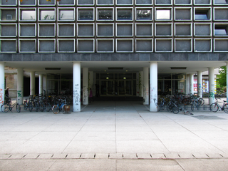
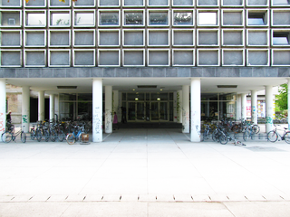
The previous version of the tutorial on restoring orthogonality used a trial and error method together with an overlaid grid to estimate the magnitude of the coefficient B alone. Interestingly, although this method is subjective and thus susceptible to bias, the estimated value of B = -0.016 is close to the value obtained by least squares of B = -0.01556. However, the lens used had a significant fifth power term that went uncorrected. This can clearly be seen in this example, where both the lines near the centre of the image and the lines towards the upper corners curve upwards. Correcting with a larger value of B would result in the lines near the centre being more closely correct at the cost of the lines in the corners, which would deviate more. Using the least squares method, optimal values of A = 0.0149, B = -0.04324 reduced the variation by 60% and resulted in a much squarer image:
 |
 |
 |
|||
| Original | Transformed with B = -0.01556 | Transformed with A = 0.0149, B = -0.04324 | |||
|---|---|---|---|---|---|
 |
 |
Transformed images compared by screen | Transformed images compared by grain extract | ||
The panorama freeware program Hugin has a database of lens coefficients at its disposal which can be accessed via the EXIF data to automatically assign values to Dersch's A, B and C. However, comparison of the new two images and the respective Dersch values shows that these are totally inadequate to the task. Hugin applies B = -0.00728 (A = C = 0) to images taken with a Canon SX 110; whereas the actual values are closer to A = 0.0149, B = -0.04324, C = 0. This means that the barrel distortion is not removed at all. (In the comparison, the ghost of the Correctrix image—especially the top of the building—can be seen as a straight line which the Hugin image converges to only in the middle.)
 |
 |
 |
|||
| Original | Manipulated with Hugin using lens values supplied | Manipulated with Correctrix, debarrel only | |||
|---|---|---|---|---|---|
 |
 |
||||
| Differential image screen | Differential image grain extract | ||||
Hugin can apparently be used to calibrate an unknown lens by estimating the coefficients using horizontal and vertical straight lines in a single image. However, salient instructions on how to do this successfully are few and far between (a rather cryptic example from the Hugin page is here).
PTLens (which was reviewed in the previous tutorial) supposedly supplies the lens parameters for Hugin, but,
if it does, it must be supplying two sets of data. Comparison of images simply debarreled by PTLens and Correctrix also reveal differences,
which appear to result from the application of different coefficients. The grain extract comparison images are strikingly different.
But PTLens does appear to have values closer to those required, although not nearly as exact as I have calculated them, as both inside and
outside a halo at r = 1 differences between PTLens and Correctrix start to appear in the grain extract comparisons.
As I currently have no access to the values determined by Niemann, I am unable to confirm that his values are accurate. The values are in the file
PTLens.dat and without a key to the data structure, they are not much fun to look at.
 |
|
| Debarreled with PTLens | Debarreled with Correctrix |
|---|---|
 |
 |
| Differential image screen | Differential image grain extract |
Ideally, pictures should possess the following characteristics:
| Yaw | Pitch | Roll |
|---|---|---|
 |  | 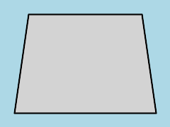 |
The basic outline of our script is thus:
<?php
extract ($_POST);
$b = "\r\n";
if (isset ($grfile_new) and $grfile_new)
{
$grfile = $grfile_new;
unset ($datarows);
}
if (isset ($grfile) and $grfile) $file = true; else $file = false;
echo "<html>$b";
echo "<head>$b";
echo "<title>Lee Traynor: Determining Dersch Coefficients</title>$b";
echo "<meta http-equiv=\"content-type\" content=\"text/html; charset=ISO-8859-1\">$b";
echo "<link rel=\"stylesheet\" type=\"text/css\" href=\"formats.css\">$b";
echo "<script type=\"text/javascript\" src=\"dersch.js\">$b";
echo "</script>$b";
echo "</head>$b";
echo "<body class=\"white\"";
if ($file) echo " onload=\"resetori ();\"";
echo ">$b";
echo "<center><h2>Lee Traynor: Determining Dersch Coefficients</h2>$b";
echo "<form method=\"post\" action=\"{$_SERVER["SCRIPT_NAME"]}\">$b";
# The main part of the program will take place here ...
echo "<table>$b";
if ((isset ($submit) and $submit != "Calculate!") or !isset ($submit))
{
if ($file) echo "<tr><th><input type=\"radio\" name=\"linetype\" value=\"line\" disabled>Trace line</th><th><input type=\"radio\" name=\"linetype\" value=\"tilt\" disabled>Tilt pairs</th></tr>$b";
echo "<tr><th>Line Trace Data ";
if ($file) echo "<input type=\"button\" onclick=\"newline ()\" value=\"New Line\"> <input type=\"button\" onclick=\"data_clear ()\" value=\"Clear Data\"> ";
echo "<input type=\"submit\" name=\"submit\" value=\"Calculate!\"></th>";
if ($file) echo "<th>Tilt Pair Data</th>";
echo "</tr>$b";
echo "<tr><th>$b<textarea name=\"datarows\" rows=\"15\" cols=\"42\">";
if (isset ($datarows)) echo $datarows;
echo "</textarea>$b</th>$b";
if ($file) echo "<th><textarea name=\"tilt\" rows=\"15\" cols=\"18\"></textarea>$b</th>$b";
echo "</tr>$b";
}
echo "<tr>$b<th";
if ($file) echo " colspan=\"2\"";
echo ">Load Image: <input type=\"file\" name=\"grfile_new\" size=\"40\">$b";
echo "<input type=\"submit\" name=\"submit\" value=\"Preview\"></th>$b</tr>$b";
echo "</table>$b";
echo "</form>$b";
?>
<hr>
</body>
</html>
Then we will need to view the top half of the image in full size. In order to estimate the pitch, the positions of point pairs at an equal radius from the centre of the image will have to be compared. This is why a semicircle is superimposed on the image. This part of the program could also be written for GD, the code for which appears later. Also we have the opportunity at this point to rotate the visible slice of the image, by selecting an angle and clicking on "Preview" again.
if ($file or (isset ($submit) and $submit == "Calculate!"))
{
switch ($submit)
{
case "Preview":
echo "<table>$b<tr><th>$grfile</th></tr>$b";
# Start section replaceable with GD
$imtemp = new Imagick ($grfile);
if ($rotate != 0) $imtemp->rotateImage ("none", $rotate);
$width = $imtemp->getImageWidth ();
$height = $imtemp->getImageHeight ();
$im = new Imagick ();
$cwidth = $width / 2;
$cheight = $height / 2;
$im->newImage ($width, $cheight, "none");
$im->compositeImage ($imtemp, imagick::COMPOSITE_OVER, 0, 0);
$imtemp->destroy ();
$draw = new ImagickDraw ();
$draw->setStrokeAntialias (true);
$draw->setStrokeColor ("yellow");
$draw->setStrokeWidth (1.5);
$draw->setFillColor ("transparent");
$draw->setStrokeAlpha (0.50);
$draw->ellipse ($cwidth, $cheight, $cheight, $cheight, 180, 360);
$im->drawImage ($draw);
$draw->destroy ();
$im->writeImage ("Sample.png");
$im->destroy ();
# End section replaceable with GD
echo "<tr>$b<td align=\"center\" valign=\"center\">$b";
echo "<img src=\"Sample.png\" onclick=\"points (event)\" style=\"cursor:crosshair\">$b</td>$b</tr>$b";
echo "<tr><td valign=\"top\">$b<input type=\"button\" onclick=\"resetori ()\" value=\"Clear tilt values\">$b";
echo "<div id=\"origin\">Origin not set</div>$b";
echo "Rotate Image by: <input type=\"radio\" name=\"rotate\" value=\"0\" selected>0° <input type=\"radio\" name=\"rotate\" value=\"90\">90° <input type=\"radio\" name=\"rotate\" value=\"180\">180° <input type=\"radio\" name=\"rotate\" value=\"270\">270°$b";
echo "</td></tr>$b</table>$b";
break;
# Other cases will be inserted here...
}
}
Replacing the Imagick with GD could be achieved with:
$im = imagecreatefrompng ($grfile);
$yellow = imagecolorallocatealpha ($im, 255, 255, 0, 64);
$black = imagecolorallocatealpha ($im, 0, 0, 0, 0);
imagealphablending ($im, true);
if ($rotate != 0) $im = imagerotate ($im, $rotate, $black);
$width = imagesx ($im);
$height = imagesy ($im);
$cwidth = $width / 2;
$cheight = $height / 2;
$imdest = imagecreatetruecolor ($width, $cheight);
imagecopy ($imdest, $im, 0, 0, 0, 0, $width, $cheight);
imagearc ($imdest, $cwidth, $cheight, $height, $height, 180, 360, $yellow);
imagepng ($imdest, "Sample.png");
imagedestroy ($im);
imagedestroy ($imdest);
Now we have the top half of our image with a yellow semicircle imposed on it at a radius, r = 1. In order to progress to the next stages of
processing, there are a couple of JavaScript issues which require attention. These scripts will be contained in one file, dersch.js
which is called in the header.
First, on loading the page with a file set, a number of variables will have to be initialised. Note how this function can also be called by a
button with the label Reset tilt values.
function resetori ()
{
if (document.getElementById ("origin"))
{
document.getElementById ("origin").innerHTML = "Origin not set";
document.forms[0].tilt.value = "";
document.forms[0].datarows.value = "";
}
orix = oriy = tilt = false;
darray = new Array (2);
}
Secondly, we have associated an event handler with our image that will react when the mouse is clicked on the image. This was also implemented for Correctrix, where the top left corner of the image was clicked on to provide the coordinates of the origin, which was followed by four further clicks for the four points of the object that was to become orthogonalised. Similarly here we will need an origin to convert the relative positions of mouse clicks into absolute positions within the image, then pairs of points in order to control for the very slight pitch the image might contain and finally to mark horizontal trace lines across the image which will provide data for iteratively calculating the Dersch coefficients. But first the origin:
function points (e)
{
if (!e) e = window.event;
theform = document.forms[0];
if (e.pageX || e.pageY)
{
posx = e.pageX;
posy = e.pageY;
}
else if (e.clientX || e.clientY)
{
posx = e.clientX + document.body.scrollLeft + document.documentElement.scrollLeft;
posy = e.clientY + document.body.scrollTop + document.documentElement.scrollTop;
}
if (document.getElementById ("origin").innerHTML == "Origin not set")
{
orix = posx;
oriy = posy;
document.getElementById ("origin").innerHTML = "Origin set: " + orix + ", " + oriy;
theform.linetype[1].disabled = false;
theform.linetype[1].checked = true;
} else
{
// Here is where the data points for pitch correction and the trace lines will be collected.
}
}
The first half of this function deals with the different ways cursor position is dealt with by the different browsers. Then, if the element named "origin" contains text to the effect that the origin has not been set, the x and y values of the origin are set and the values are displayed at the corresponding point on the form. Also the radio button above the textarea for the tilt pair data is enabled and selected, so that we can go directly to the next point we want to click on, without having to leave the image to click on the radio button to activate it.
Even if the camera was pointed "absolutely level" there still may be a residual pitch which needs to be controlled for. However, as the image has not been debarrelled we are faced with the task of choosing pairs of points on the same line which would reflect pitch alone. Such pairs can always be found at constant radii from the centre of an image since any point along a radius will be transformed by the Seidel Aberration by exactly the same amount; the difference in height divided by the distance between the points gives a measure of the pitch which can be used to calculate the pitch with the mathematical function arctangent.
First, we will need to collect point coordinates into the textarea tilt and do this systematically by choosing one point on the left side of a line followed by one point on the right side of the line where the semicircle intersects with the line. Once each point has been entered into the box, the array darray () used to collect them can be recycled. At the part of the points (e) function where the data points will be collected we include (after else):
{
darray[0] = posx - orix;
darray[1] = posy - oriy;
if (theform.linetype[1].checked)
{
if (theform.tilt.value != "") theform.tilt.value += "\n";
theform.tilt.value += darray[0] + "\t" + darray[1];
} else
{
// This is where the data points for the trace lines will be collected.
}
darray = new Array (2);
}
When adding coordinates to the tilt textarea, JS first sees whether there is something in the box and if so, adds a line break to the end before
adding the data separated by a tab stop. This will prevent later grief when splitting apart the data.
When all the pairs of points have been collected, we switch to collecting data for the trace lines and that will always have to start with creating
a new line. So, instead of formally completing the process and starting a new line, we can do both at the same time by clicking on "New
Line", which will call a JavaScript function.
The newline () function will have to do four things:
function newline ()
{
theform = document.forms[0];
if (!orix) alert ("Set origin first!"); else
{
theform.datarows.value = theform.datarows.value + "NL\r\n";
if (theform.linetype[0].disabled)
{
theform.linetype[0].disabled = false;
theform.linetype[0].checked = true;
}
if (!tilt)
{
tilt = 0;
tiltpairs = theform.tilt.value.split ("\n");
for (i = 0; i < tiltpairs.length / 2; i++)
{
p = tiltpairs[(2*i)].split ("\t");
q = tiltpairs[(2*i+1)].split ("\t");
tilt += Math.atan ((q[1] - p[1])/(p[0] - q[0]));
}
tilt = tilt * 2 / tiltpairs.length;
theform.tilt.value = tilt + " rad";
}
}
}
Next, any number of points along a well defined horizontal line is clicked through: just start on the left (or, indeed right) and click on a
particular line, progressing more or less regularly. This is the trace line. When finished with one line, click on "New line" again to
start another set of data.
This coordinate data is transformed into polar coordinates and consecutively added to the textarea datarows. Using polar coordinates
it is quite simple to add the predetermined pitch. Later, polar coordinates can be converted back into orthogonal coordinates. The trace lines are
collected within the points (e) function with:
{
img = window.document.images[0];
hd1 = img.width / 2 - darray[0];
vd1 = img.height - darray[1];
r1 = Math.sqrt (Math.pow (hd1, 2) + Math.pow (vd1, 2));
theta = Math.acos (vd1 / r1);
if (darray[0] < img.width / 2) theta = -theta;
theta = theta + tilt;
r1 = r1 / img.height;
theform.datarows.value = theform.datarows.value + r1 + "\t" + theta + "\r\n";
}
And, as a final point, if all the data in datarows needs to be cleared, there is the function data_clear ():
function data_clear ()
{
document.forms[0].datarows.value = "";
darray = new Array (2);
newline ();
}


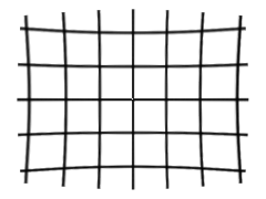
An image with the trace lines imposed in red (left). Trace lines were mapped with InterDraw, rotated by the negative pitch of the shot (0.43539°)
and imposed on the original with GIMP at a transparency of 75%. You get get the current program to do this for you, but that would be a task for an
exercise. The individual trace lines after levelling are represented in black on the right.
Now we will move on to the task of finding coefficients for the Dersch (Multiplicative) and Inverse (Divisive) transformations to straighten out
these lines as nearly as possible.

The optical parameters for the lens were used to manipulate a grid in a similar way to reverse engineering the Dersch transformation and then the trace lines which were the source of the calculations in the last three seections were reimposed in red on the grid showing good fit.
Develop ImageMagick distortImage() constants to deal with Seidel Aberrations directly.
Use several radii when estimating pitch to control for yaw as well.